How to Shoot Grade With Precision: A Complete Guide for Contractors and Homeowners
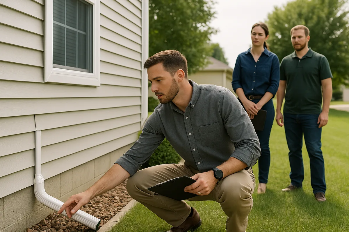
Knowing how to shoot grade is one of the most fundamental skills in construction, landscaping, and drainage work. Whether you're a contractor preparing a building pad, a homeowner regrading a yard for better drainage, or an inspector verifying lot elevations, the ability to accurately measure and establish grade determines the success of virtually every outdoor project. Poor grading leads to standing water, foundation damage, erosion, and costly rework. Precise grading prevents all of it.
This guide walks through every aspect of shooting grade—from selecting the right instrument and establishing benchmarks to executing field measurements and translating readings into actionable earthwork. We'll cover both traditional and modern site grading techniques, explain the math behind slope calculations, and share the professional practices that separate reliable grading from guesswork.
Understanding What It Means to Shoot Grade
At its core, shooting grade is the process of measuring the elevation of points on the ground relative to a known reference point. By comparing these elevations, you can determine how much the ground rises or falls across a site, calculate slopes, and establish the target elevations needed for proper drainage, foundation placement, or road construction.
The term "shoot" comes from the act of sighting through an optical instrument—or intercepting a laser plane—to read a measurement on a graduated rod held at a specific location. Each reading tells you how high or low that point is relative to the instrument's line of sight. When you collect enough of these readings across a site, you build a three-dimensional picture of the terrain.
The Difference Between Existing Grade and Finish Grade
Two terms you'll encounter constantly in contractor grading are existing grade and finish grade. Existing grade (also called natural grade or original grade) is the current elevation of the ground surface before any work is done. Finish grade is the planned final elevation after earthwork is complete. The difference between the two at any given point tells you how much material needs to be cut (removed) or filled (added).
For example, if your existing grade at a stake reads 98.50 feet and your finish grade plan calls for 99.00 feet at that same location, you need 6 inches of fill. If the plan calls for 97.75 feet, you need to cut 9 inches. This cut-and-fill calculation is the practical output of shooting grade, and it drives every decision about equipment, material hauling, and compaction.
Why Precision Matters for Drainage
Drainage is unforgiving. Water flows downhill, and it only takes a small error—sometimes as little as half an inch over a 10-foot span—to reverse the intended flow direction. When you're establishing a 2% slope for a swale or ensuring the code-required 5% grade away from a foundation, your measurements need to be accurate to within fractions of an inch. This is why professional-grade instruments and disciplined field procedures aren't optional—they're essential.
Get Your Drainage Intelligence Report™
Start a free trial and generate reports on demand.
Essential Tools for Shooting Grade
The quality and type of instrument you use directly impacts the accuracy, speed, and reliability of your grading work. Here's a breakdown of the primary tools used in modern laser level grading and traditional grade shooting.
Rotary Laser Levels
The rotary laser level has become the dominant tool for contractor grading on residential and light commercial sites. It projects a 360-degree horizontal (or slope-matched) plane of laser light across the work area. A detector mounted on a grade rod picks up this laser plane and indicates whether the rod is above, below, or exactly on the level line.
Key specifications to evaluate when selecting a rotary laser level include:
- Accuracy: Look for ±1/8 inch at 100 feet for general grading; ±1/16 inch at 100 feet for precision work like foundation pads and concrete flatwork.
- Range: Most construction-grade rotary lasers work effectively at 200–1,000 feet with a detector. For residential lots, 200–500 feet is typically sufficient.
- Self-leveling: Modern units self-level within a range of ±5° using an internal compensator. This saves significant setup time and reduces operator error.
- Slope capability: Some models allow you to disengage the compensator on one or both axes to set a specific slope, which is invaluable for grading drainage swales and parking areas.
Popular professional-grade brands include Spectra Precision, Topcon, Leica, and DeWalt. For homeowner-level work, units from Bosch and Johnson Level offer good accuracy at lower price points.
Builder's Levels and Transit Levels
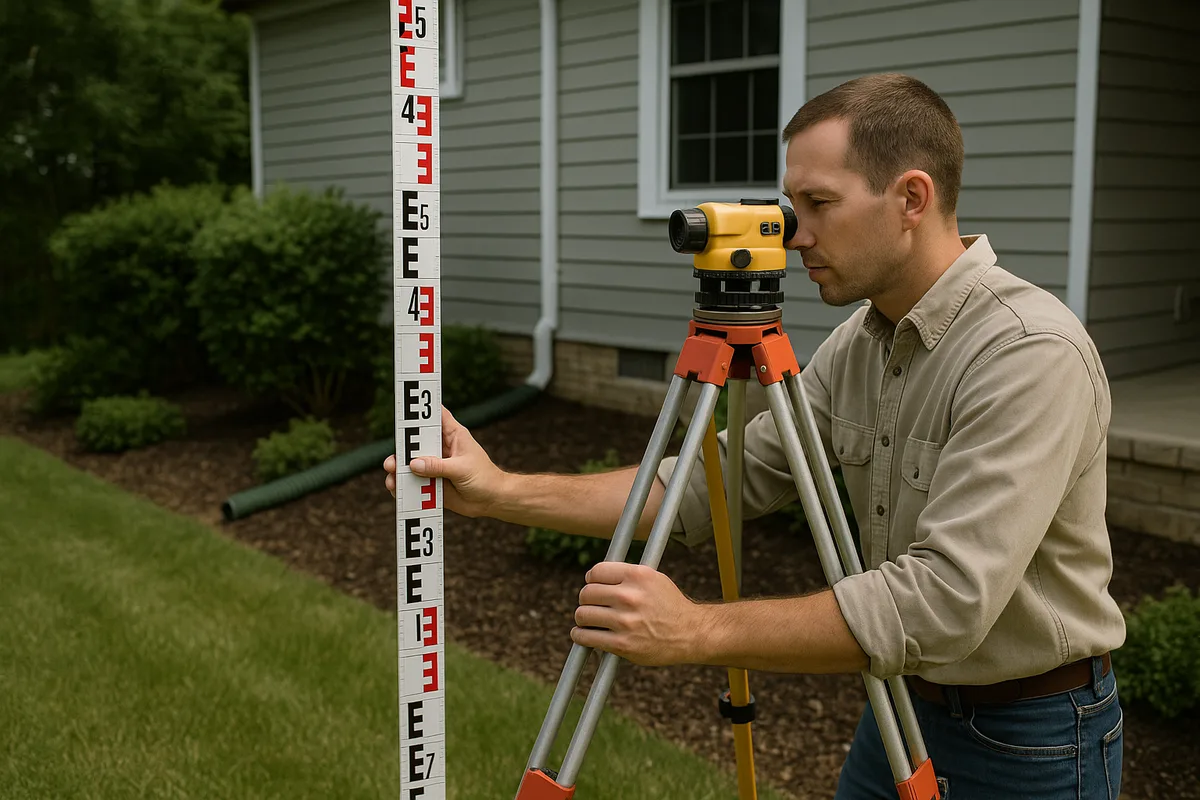
Before laser technology became affordable, the builder's level (also called a dumpy level) and the transit level were the standard instruments for shooting grade. A builder's level is an optical telescope mounted on a leveling base that establishes a perfectly horizontal line of sight. The operator looks through the eyepiece and reads the numbers on a grade rod held at the target point.
A transit level adds the ability to tilt the telescope vertically, making it useful for plumbing walls and measuring vertical angles in addition to shooting grade. Both instruments remain viable and are often preferred in certain situations:
- They don't require batteries
- They work in any lighting condition (lasers can be hard to detect in bright sunlight)
- They provide direct visual confirmation of readings
- They're generally less expensive than quality rotary lasers
The trade-off is speed—optical instruments require the operator to be at the instrument for every reading, while laser levels allow the rod person to work independently with a detector.
Grade Rods and Accessories
The grade rod (or leveling rod) is the other half of the equation. Standard rods are graduated in feet, tenths, and hundredths of a foot (not inches) for construction work, though metric and architectural-scale rods are also available. Most professional rods are made of fiberglass or aluminum and extend from 8 to 25 feet in telescoping sections.
Additional tools you'll need include:
- Tripod: A heavy-duty, flat-head or dome-head tripod appropriate for your instrument. Stability is paramount—a wobbly tripod ruins accuracy.
- Laser detector (receiver): Clamps to the rod and provides audible and visual indication of the laser plane. Essential for outdoor work where the laser dot is invisible.
- Grade stakes and hubs: Wooden stakes (typically 1×2 or 2×2 lumber) driven into the ground to mark survey points. Hubs are shorter, thicker stakes driven flush with the ground to serve as semi-permanent elevation reference points.
- Marking paint and flagging tape: For identifying stake locations and communicating cut/fill information to equipment operators.
- Field book or digital recorder: For recording all readings systematically.
Setting Up Your Instrument and Establishing a Benchmark
Proper setup is where precision begins. Rushing through instrument placement and benchmark establishment is the most common source of grading errors.
Choosing an Instrument Location
Position your laser level or builder's level near the center of the area you'll be grading, on firm ground that won't settle under the tripod's weight. Avoid setting up on freshly placed fill, soft soil, or surfaces subject to vibration from nearby traffic or equipment. The instrument should have a clear line of sight to all points you need to measure—remember that laser beams and optical sightlines travel in straight lines and can't bend around obstacles.
For large sites, you may need to move the instrument to multiple positions. When you do, always tie back to your benchmark (more on this below) to ensure continuity of your elevation data.
Leveling the Instrument
If you're using a self-leveling laser, place it on the tripod, turn it on, and allow the internal compensator to settle. Most units indicate when they're level with a steady light or by beginning to rotate. If the unit is too far out of level for the compensator to handle, adjust the tripod legs until the bubble on the base plate is roughly centered.
For optical instruments, you'll level using the four leveling screws on the base plate and the bubble vial. Turn the telescope parallel to one pair of opposing screws and adjust them until the bubble is centered. Rotate 90° and repeat with the other pair. Continue alternating until the bubble stays centered through a full 360° rotation.
Establishing a Benchmark
A benchmark (BM) is a point of known or assumed elevation that serves as the reference for all your measurements. On professional survey jobs, benchmarks are tied to published geodetic control points, such as those maintained by the National Geodetic Survey (NGS). For most residential grading projects, you'll establish a local benchmark—a stable, permanent point that won't be disturbed during construction.
Good benchmark locations include:
- A nail driven into the base of a large tree
- A mark chiseled into a concrete curb, sidewalk, or foundation
- A rebar or iron pipe driven deep into undisturbed ground
- An existing survey monument
You can assign your benchmark any convenient elevation. If you have survey data, use the published elevation. If not, many contractors assign an arbitrary value like 100.00 feet to keep all numbers positive and easy to work with.
To establish your instrument's Height of Instrument (HI), have the rod person hold the grade rod on the benchmark while you take a reading. If your benchmark elevation is 100.00 feet and you read 4.62 on the rod, your HI is 104.62 feet. This number is the elevation of your laser plane or line of sight, and every subsequent reading is subtracted from it to determine ground elevation.
Step-by-Step Process to Shoot Grade
With your instrument set up and benchmark established, you're ready to begin collecting elevation data. Here's the systematic process used in professional site grading techniques.
Step 1: Record the Backsight and Calculate Height of Instrument
The first reading you take—on your benchmark—is called the backsight (BS). This reading, added to the benchmark elevation, gives you the Height of Instrument.
HI = Benchmark Elevation + Backsight Reading
Example: BM = 100.00, BS = 5.23, so HI = 105.23
Write this down prominently in your field book. Every subsequent calculation depends on this number.
Step 2: Take Foresight Readings at Target Points
Now the rod person moves to each point where you need an elevation. These readings are called foresights (FS). At each point, the rod is held plumb (vertically) on the ground surface, and you either read the rod through the telescope or note where the laser detector locks on.
Ground Elevation = HI – Foresight Reading
Example: HI = 105.23, FS = 6.48, so Ground Elevation = 98.75
If the foresight reading is large, it means the ground is low relative to the instrument. If the reading is small, the ground is high. This inverse relationship trips up beginners, so take time to internalize it.
Step 3: Record and Organize Data Systematically
For each point, record:
- Point identification (stake number, grid reference, or description like "NE corner of house")
- Rod reading (foresight value)
- Calculated elevation
- Finish grade elevation (from the grading plan)
- Cut or fill (difference between existing and finish grade)
A typical field book entry might look like:
| Point | FS Reading | Elevation | Finish Grade | Cut/Fill |
|---|---|---|---|---|
| Stake 1 | 6.48 | 98.75 | 99.00 | +0.25 Fill |
| Stake 2 | 5.91 | 99.32 | 99.00 | -0.32 Cut |
| Stake 3 | 7.12 | 98.11 | 98.50 | +0.39 Fill |
Step 4: Close the Loop
After taking a series of foresight readings, return to the benchmark and take another reading. This closing shot should match your original backsight reading within your instrument's stated accuracy. If the closing shot is off by more than 0.02–0.03 feet, something has changed—the tripod may have settled, the instrument may have been bumped, or the benchmark may have been disturbed. In that case, you need to investigate and potentially reshoot your points.
This verification step is non-negotiable in professional practice. Skipping it means you have no way to confirm the reliability of your data.
Grade Staking: Communicating Elevations in the Field
Once you've shot the existing grade and calculated cuts and fills, the next step is grade staking—placing marked stakes in the ground that communicate elevation information to equipment operators and other crew members.
Anatomy of a Grade Stake
A properly set grade stake typically consists of two components:
The hub: A short (12–18 inch) wooden stake driven nearly flush with the ground. A nail is driven into the top of the hub to mark the exact point where the elevation was measured. The top-of-nail elevation is recorded.
The guard stake (lath): A taller stake (3–4 feet) driven at an angle next to the hub. The guard stake serves two purposes: it makes the hub visible from a distance, and it provides a surface for writing cut/fill information.
Marking Conventions
The construction industry uses standardized marking conventions on guard stakes that every experienced operator understands:
- C 0.8 means "Cut 0.8 feet" — remove 0.8 feet of material to reach finish grade
- F 1.2 means "Fill 1.2 feet" — add 1.2 feet of material to reach finish grade
- A blue top on the stake (painted or flagged) typically indicates fill
- A red top indicates cut
- An arrow on the guard stake points toward the hub
Some contractors also write the finish grade elevation on the back of the guard stake for reference. The more information you provide clearly, the fewer mistakes the equipment operator will make.
Grid Staking vs. Key-Point Staking
For large, relatively uniform areas (like building pads or parking lots), stakes are often placed on a regular grid—typically 25 or 50 feet apart. This gives the equipment operator consistent reference points across the entire work area.
For residential drainage work, key-point staking is more common. You place stakes at critical locations:
- Building corners and midpoints of long walls
- High and low points of swales
- Inlet and outlet of drainage structures
- Property corners and easement boundaries
- Transitions between different slope gradients
- Locations where drainage flow direction changes
Calculating and Setting Slopes for Drainage
Shooting grade isn't just about measuring what exists—it's about establishing the elevations needed for water to flow where you want it. Understanding slope calculation is essential for effective laser level grading on drainage projects.
Slope Expressed as Percentage, Ratio, and Inches Per Foot
Slope can be expressed in several ways, and you need to be fluent in converting between them:
- Percentage: Rise divided by run, multiplied by 100. A 2% slope falls 2 feet over 100 feet of horizontal distance.
- Ratio: Expressed as rise:run. A 2% slope is a 1:50 ratio (1 foot of fall per 50 feet of run).
- Inches per foot: Common in plumbing and small-scale grading. A 2% slope equals approximately 1/4 inch per foot.
For residential drainage, the most commonly specified slopes are:
- Foundation perimeter grading: 5% minimum (6 inches in 10 feet) per IRC code requirements
- Yard swales and drainage channels: 1–2% minimum; 2–5% is ideal
- Driveways and walkways: 1–2% cross-slope for sheet drainage; 0.5–8% longitudinal slope
- French drain trench bottoms: 0.5–1% minimum toward the outlet
- Gutter and downspout discharge areas: 2% minimum away from the structure
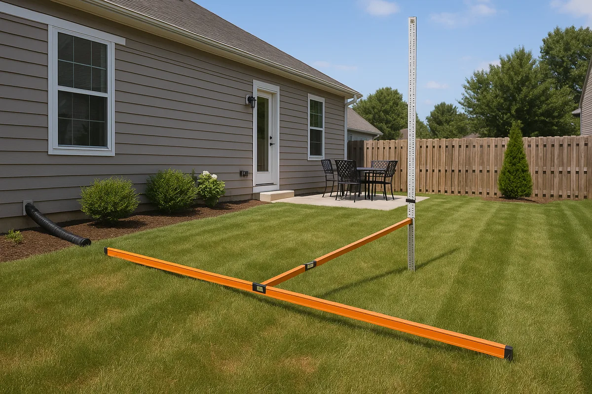
Setting a Slope With a Laser Level
Many rotary laser levels have a slope-matching or grade-matching feature that lets you tilt the laser plane to project a sloped reference instead of a level one. Here's how to use it:
- Set the laser over your starting point (typically the high end of the desired slope)
- Engage the slope mode (this disengages the self-leveling compensator on one axis)
- Use the instrument's slope dial or remote control to set the desired gradient—for example, 2.00%
- The laser now projects a plane that falls at exactly 2% along the selected axis
- The rod person can now move along the slope line, and a consistent detector reading means the ground matches the target slope
If your laser doesn't have slope capability, you can achieve the same result mathematically. Keep the laser level (horizontal) and calculate the target rod reading at each stake based on its distance from the reference point:
Target Rod Reading = Reference Rod Reading + (Distance × Slope)
For a 2% slope: at 25 feet from the reference, the rod reading should be 0.50 feet higher than at the reference point (25 × 0.02 = 0.50). At 50 feet, it should be 1.00 foot higher.
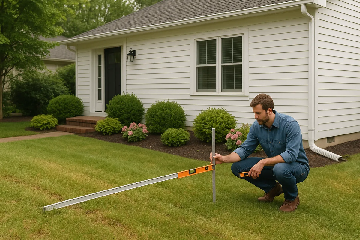
Checking Cross-Slopes and Compound Grades
Many grading situations involve slopes in two directions simultaneously—a compound grade. A driveway, for example, might slope 4% from the garage toward the street while also sloping 2% from the center toward the edges for cross-drainage. To verify compound grades, you need to shoot points on a grid pattern and confirm that both the longitudinal and transverse slopes meet specifications at every point.
This is where meticulous record-keeping becomes critical. Create a grid map in your field book showing the elevation at each intersection point, then calculate slopes between adjacent points in both directions.
Common Mistakes and How to Avoid Them
Even experienced professionals make grading errors. Here are the most frequent mistakes in shooting grade and the practices that prevent them.
Rod Not Held Plumb
If the grade rod tilts even slightly, the reading will be too high (the apparent rod reading increases as the rod leans). On a 10-foot rod, a 5-degree tilt introduces an error of about 0.05 feet—enough to compromise drainage slopes. Always use a rod level (a circular bubble attached to the rod) and ensure the rod person keeps the bubble centered for every reading.
Alternatively, the rod person can slowly rock the rod forward and backward through the plumb position. The lowest reading observed during the rock is the true plumb reading. This technique is standard practice with optical instruments.
Instrument Settlement
Tripods set on soft ground, fresh fill, or asphalt on hot days can settle gradually, causing all readings taken after the settlement to be incorrect. Mitigate this by:
- Pressing the tripod legs firmly into the ground during setup
- Placing the tripod feet on stable surfaces (plywood pads on soft ground)
- Checking back to the benchmark frequently
- Allowing the tripod to settle for a few minutes before beginning readings
Misreading the Rod
With optical instruments, misreading the rod is surprisingly common, especially at longer distances where the numbers appear small in the telescope. The most frequent error is reading the wrong foot mark—for example, reading 4.32 when the actual value is 5.32. Always count the foot marks carefully from the bottom of the rod, and have the rod person confirm by holding a hand at the approximate reading height.
With laser detectors, the most common error is failing to recalibrate the detector's on-grade window. A detector set for a wide window (±0.5 inch) will show "on grade" across a full inch of range, which may be too imprecise for drainage work. Tighten the detection window to ±1/8 inch or finer for critical grading.
Ignoring Soil Conditions
Shooting grade tells you the elevation of the current ground surface, but it doesn't tell you what's beneath it. If you're grading over recently placed fill that hasn't been compacted, the surface will settle after your grading work is complete, potentially reversing slopes and creating low spots. Always verify that the subgrade is properly compacted before establishing finish grade elevations. The NRCS Web Soil Survey can help you understand the native soil characteristics on your site, including shrink-swell potential and drainage class, which affect how the soil will behave after grading.
Not Accounting for Topsoil and Finish Materials
If your finish grade plan accounts for 4 inches of topsoil and sod, you need to set your rough grade 4 inches below the target finish elevation. This sounds obvious, but it's frequently overlooked, especially when different trades are responsible for rough grading and finish work. Clearly document whether elevations on your grade stakes refer to rough grade or finish grade.
Advanced Techniques and Modern Technology
While the fundamental principles of shooting grade haven't changed in centuries, the tools and techniques available today offer unprecedented efficiency and accuracy.
GPS and GNSS Machine Control
On larger projects, GPS-based machine control systems have revolutionized grading. These systems mount GNSS receivers on excavators, dozers, and motor graders, providing real-time elevation data to the operator's cab display. The machine's blade or bucket position is compared against the digital grading plan, and the operator (or automatic system) adjusts accordingly.
For residential work, GPS machine control is generally overkill, but some progressive contractors use it for large subdivision grading where the efficiency gains justify the equipment cost. The accuracy of survey-grade GNSS is typically ±0.03 feet vertically—comparable to a well-operated laser level.
Drone-Based Topographic Surveys
Drone photogrammetry and LiDAR scanning can capture existing grade across an entire property in minutes, producing detailed topographic maps with contour intervals as tight as 0.5 feet. While drones don't replace boots-on-the-ground grade staking, they provide excellent pre-construction data and post-construction verification.
The elevation data captured by drones can be compared against datasets from the USGS 3D Elevation Program (3DEP) to verify accuracy and provide regional topographic context for your site.
Digital Field Recording
Traditional field books are being supplemented (and sometimes replaced) by tablet-based applications that allow you to record readings, calculate elevations automatically, generate cut/fill reports, and overlay data on aerial imagery or site plans in real time. These tools reduce math errors and make it easy to share data with other team members, engineers, and inspectors.
However, always maintain a paper backup. Tablets run out of battery, get dropped in mud, and crash at inconvenient times. The field book remains the most reliable recording device ever invented.
Shooting Grade for Specific Drainage Features
Different drainage features require different grading approaches:
- Swales: Shoot the centerline and both lip elevations at regular intervals (typically every 25 feet). The cross-section should show a smooth, parabolic or V-shaped profile with consistent longitudinal slope along the centerline.
- Berms: Shoot the top of berm, both toes, and intermediate points. Verify that the berm height meets design specifications and that the back side slopes away from the protected area.
- Retention/detention basins: Establish the invert (lowest point), overflow elevation, and side slopes. Shoot a grid across the basin floor to verify uniform grade toward the outlet.
- French drain trenches: Shoot the trench bottom at the inlet and outlet, and at intermediate points to verify consistent slope. Even a short section of reverse slope will trap water and reduce system effectiveness.
Putting It All Together: A Residential Grading Workflow
Let's walk through a complete residential grading scenario to show how all these elements connect in practice.
Imagine you're regrading a backyard that currently slopes toward the house, causing water to pool against the foundation. Your goal is to reverse the slope so water flows away from the foundation toward a drainage swale at the rear of the property.
Phase 1: Assess Existing Conditions
Set up your laser level in the center of the yard. Establish a benchmark on a stable feature—say, a nail in the concrete patio, assigned elevation 100.00. Shoot existing grade at the foundation wall, at 5-foot intervals across the yard, and at the rear property line. Record all readings and calculate elevations.
Your data might reveal that the ground at the foundation is at 99.50, while the ground 10 feet out is at 99.75—a reverse slope of 2.5% toward the house. At the rear property line (60 feet from the foundation), the elevation is 99.00.
Phase 2: Develop a Grading Plan
You need the ground at 10 feet from the foundation to be at least 6 inches below the foundation elevation (which is at 100.25, measured at the top of the slab). So the ground at the foundation wall should be no higher than 99.75, falling to 99.25 at 10 feet out—a 5% slope. Beyond 10 feet, you can reduce to a 2% slope toward the rear swale.
Calculate the finish grade elevation at each stake location and determine cuts and fills.
Phase 3: Set Grade Stakes
Drive hubs and guard stakes at each critical point. Mark each guard stake with the cut or fill required. Use blue flagging for fill areas and red for cut areas. Set string lines between stakes along critical slope lines so the equipment operator has visual references.
Phase 4: Execute Earthwork and Verify
After the equipment operator moves the dirt, reshoot every stake to verify that finish grade elevations have been achieved within tolerance (typically ±0.05 feet for residential grading). Pay special attention to the critical first 10 feet from the foundation and the swale centerline.
Phase 5: Final Documentation
Record all final as-built elevations. This documentation is valuable for future reference, property sales, and any warranty or dispute resolution. If you're working with an inspector, these records demonstrate code compliance.
Precise grading isn't just about moving dirt—it's about controlling water. Every reading you take, every stake you set, and every slope you establish determines where water will go for the life of the property. The time invested in shooting grade correctly pays dividends for decades.
At Low Point Labs, we specialize in topographic drainage intelligence that gives homeowners, contractors, and inspectors the elevation data they need to make confident grading decisions. Whether you're planning a regrading project, verifying existing slopes, or investigating drainage problems, our detailed drainage assessments provide the precise, actionable information that turns guesswork into engineered solutions. Explore our services to see how precision topographic data can transform your next grading project.
Get Your Drainage Intelligence Report™
Start a free trial and generate reports on demand.
Frequently Asked Questions
Related Articles
How Much Slope Does a Yard Need for Proper Drainage?
Understanding Slope and Grade Around Your Home: A Complete Guide